- 您现在的位置:买卖IC网 > Sheet目录1994 > DS1647P-120 (Maxim Integrated Products)IC RAM TIMEKEEP NV 120NS 34-PCM
DS1647/DS1647P
5 of 12
SETTING THE CLOCK
The MSB Bit, B7, of the control register is the write bit. Setting the write bit to a 1, like the read bit halts
updates to the DS1647 registers. The user can then load them with the correct day, date and time data in
24-hour BCD format. Resetting the write bit to a 0 then transfers those values to the actual clock counters
and allows normal operation to resume.
STOPPING AND STARTING THE CLOCK OSCILLATOR
The clock oscillator may be stopped at any time. To increase the shelf life, the oscillator can be turned off
to minimize current drain from the battery. The OSC bit is the MSB for the second’s registers. Setting it
to a 1 stops the oscillator.
FREQUENCY TEST BIT
Bit 6 of the day byte is the frequency test bit. When the frequency test bit is set to logic 1 and the
oscillator is running, the LSB of the second’s register will toggle at 512Hz. When the seconds register is
being read, the DQ0 line will toggle at the 512Hz frequency as long as conditions for access remain valid
(i.e., CE low, OE low, and address for seconds register remain valid and stable).
CLOCK ACCURACY (DIP MODULE)
The DS1647 is guaranteed to keep time accuracy to within ±1 minute per month at +25°C. The RTC is
calibrated at the factory by Dallas Semiconductor using nonvolatile tuning elements, and does not require
additional calibration. For this reason, methods of field clock calibration are not available and not
necessary. Clock accuracy is also affected by the electrical environment and caution should be taken to
place the RTC in the lowest-level EMI section of the PC board layout. For additional information, refer
to Application Note 58.
CLOCK ACCURACY (POWERCAP MODULE)
The DS1647 and DS9034PCX are each individually tested for accuracy. Once mounted together, the
module will typically keep time accuracy to within ±1.53 minutes per month (35ppm) at +25°C. Clock
accuracy is also affected by the electrical environment and caution should be taken to place the RTC in
the lowest-level EMI section of the PC board layout. For additional information, refer to Application
Note 58.
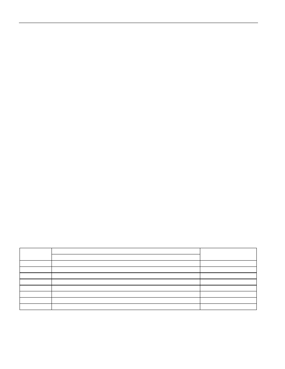
Table 2. Register Map—BANK1
ADDRESS
DATA
FUNCTION
B7
B6
B5
B4
B3
B2
B1
B0
7FFFF
—
Year
00–99
7FFFE
X
—
Month
01–12
7FFFD
X
—
Date
01–31
7FFFC
X
FT
X
—
Day
01–07
7FFFB
X
—
Hour
00–23
7FFFA
X
—
Minutes
00–59
7FFF9
OSC
—
Seconds
00–59
7FFF8
W
R
X
Control
A
OSC
= STOP BIT
R = READ BIT
FT = FREQUENCY TEST
W = WRITE BIT
X = UNUSED
Note:
All indicated “X” bits are unused, but must be set to “0” when written to ensure proper clock operation.
发布紧急采购,3分钟左右您将得到回复。
相关PDF资料
DS1670S
IC CTRLR SYSTEM PORTABLE 20-SOIC
DS1672S-3/T&R
IC TIMEKEEPER 3V 32-BIT 8-SOIC
DS1673S-3
IC CTRLR SYSTEM PORT 3V 20-SOIC
DS1677E
IC CTRLR SYSTEM PORT 20-TSSOP
DS1678S/T&R
IC RECORDER REALTIME EVENT 8SOIC
DS1682S
IC TIMEKEEPER ALARM ELAPSE 8SOIC
DS1683S+T&R
IC REAL TIME EVENT REC 8SOIC
DS1685EN-5/T&R
IC RTC 5V 64BIT Y2K IND 24TSSOP
相关代理商/技术参数
DS1647P-120+
功能描述:实时时钟 NV Timekeeping RAM RoHS:否 制造商:Microchip Technology 功能:Clock, Calendar. Alarm RTC 总线接口:I2C 日期格式:DW:DM:M:Y 时间格式:HH:MM:SS RTC 存储容量:64 B 电源电压-最大:5.5 V 电源电压-最小:1.8 V 最大工作温度:+ 85 C 最小工作温度: 安装风格:Through Hole 封装 / 箱体:PDIP-8 封装:Tube
DS1648
制造商:NSC 制造商全称:National Semiconductor 功能描述:TRI-STATE TTL to MOS Multiplexers/Drivers
DS1648J
制造商:未知厂家 制造商全称:未知厂家 功能描述:2-Input Digital Multiplexer
DS1648J/A+
制造商:未知厂家 制造商全称:未知厂家 功能描述:2-Input Digital Multiplexer
DS1649
制造商:NSC 制造商全称:National Semiconductor 功能描述:Hex TRI-STATEE TTL to MOS Drivers
DS1649J
制造商:NSC 制造商全称:National Semiconductor 功能描述:Hex TRI-STATEE TTL to MOS Drivers
DS1649J/883
制造商:未知厂家 制造商全称:未知厂家 功能描述:Memory Driver
DS1649J/A+
制造商:未知厂家 制造商全称:未知厂家 功能描述:Memory Driver